Getting started
Zeugwerk-Development-Kit is a fully integrated application framework with easy to use tools for automation engineers. The kit provides a maintainable, modular and standardized environment for Automation Solutions and comes with
- a set of comprehensive and tested PLC-libraries
- an application template that is suiteable for any kind of machine
- an integrated development extension called Zeugwerk-Creator
- and many other tools to make developing a breeze
- a
Quickstart Tutorialto be able to play with in under 5 minutes
Installation
First, download the latest Release of Zeugwerk Development Kit, then follow the installation instructions (see Installation Guide for details)
Setup
Zeugwerk Development Kit installs a Quickstart Application, which will be covered in this guide. To create this application
- Create a new
TwinCAT XAE Project (XML format)solution - In
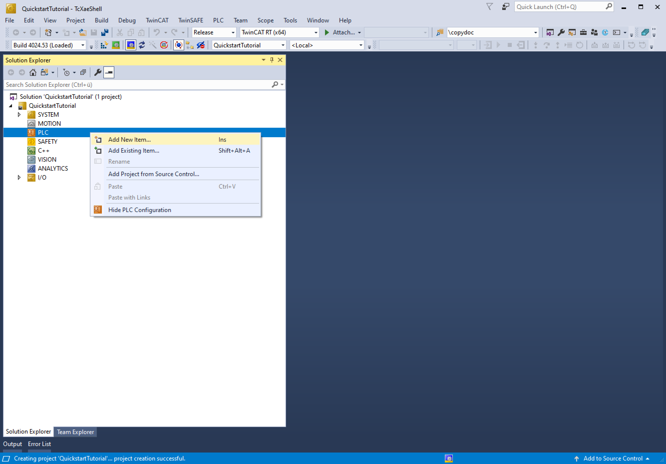
Solution Explorerright click onPLCnode and click onAdd New Itemand choosePlc Templates->Zeugwerk Quickstart->Zeugwerk Quickstartand give this PLC project the nameQuickstartTutorial - Now Activate the trial license which you should have received via Email under
Tools->Zeugwerk Creator->License.


Restore Zeugwerk Framework
Use Twinpack to restore the libraries of Zeugwerk Framework
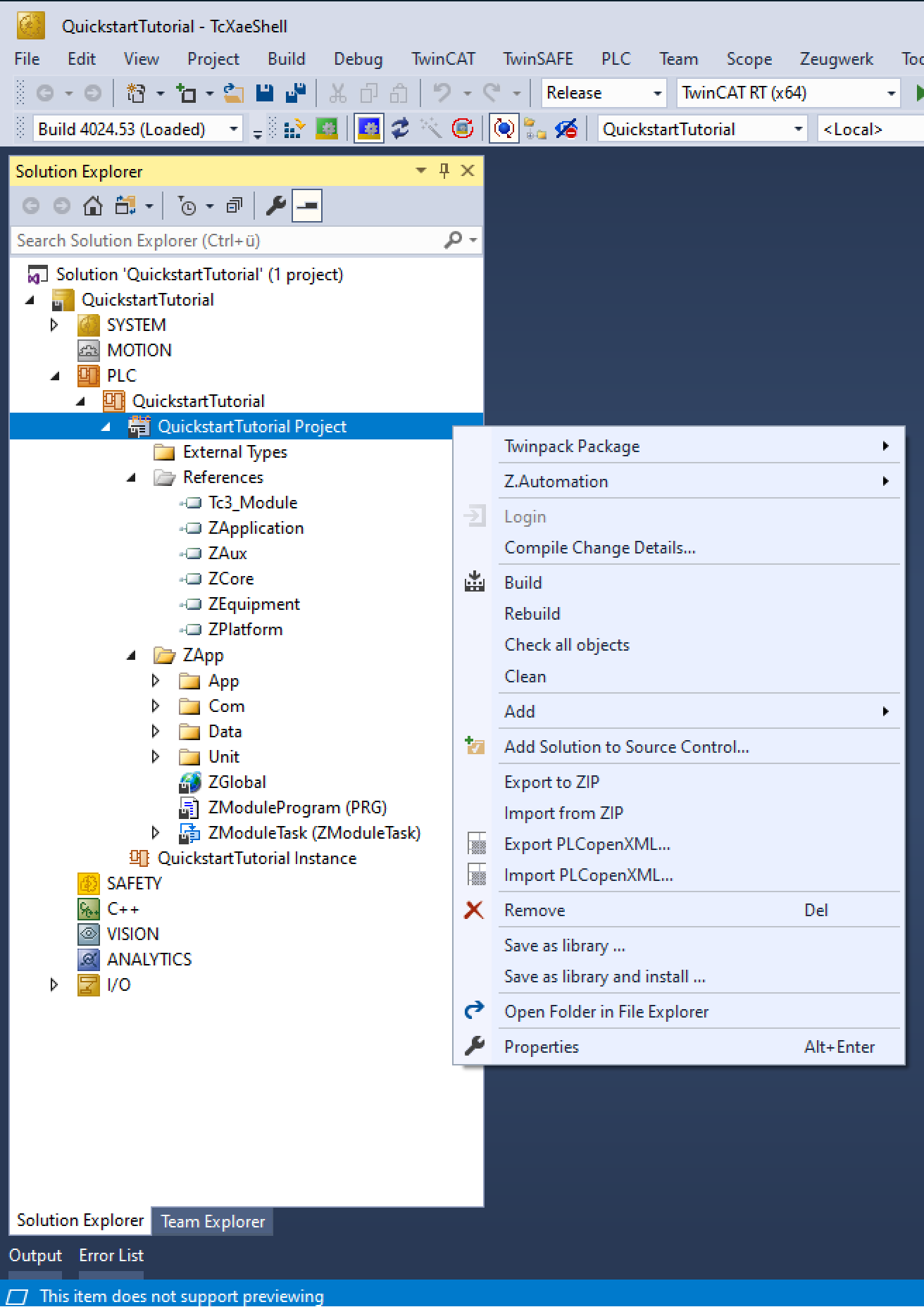
- Open
PLCnode inSolution Explorerand step down the hierarchy until you seeReferencesnode - Right click on
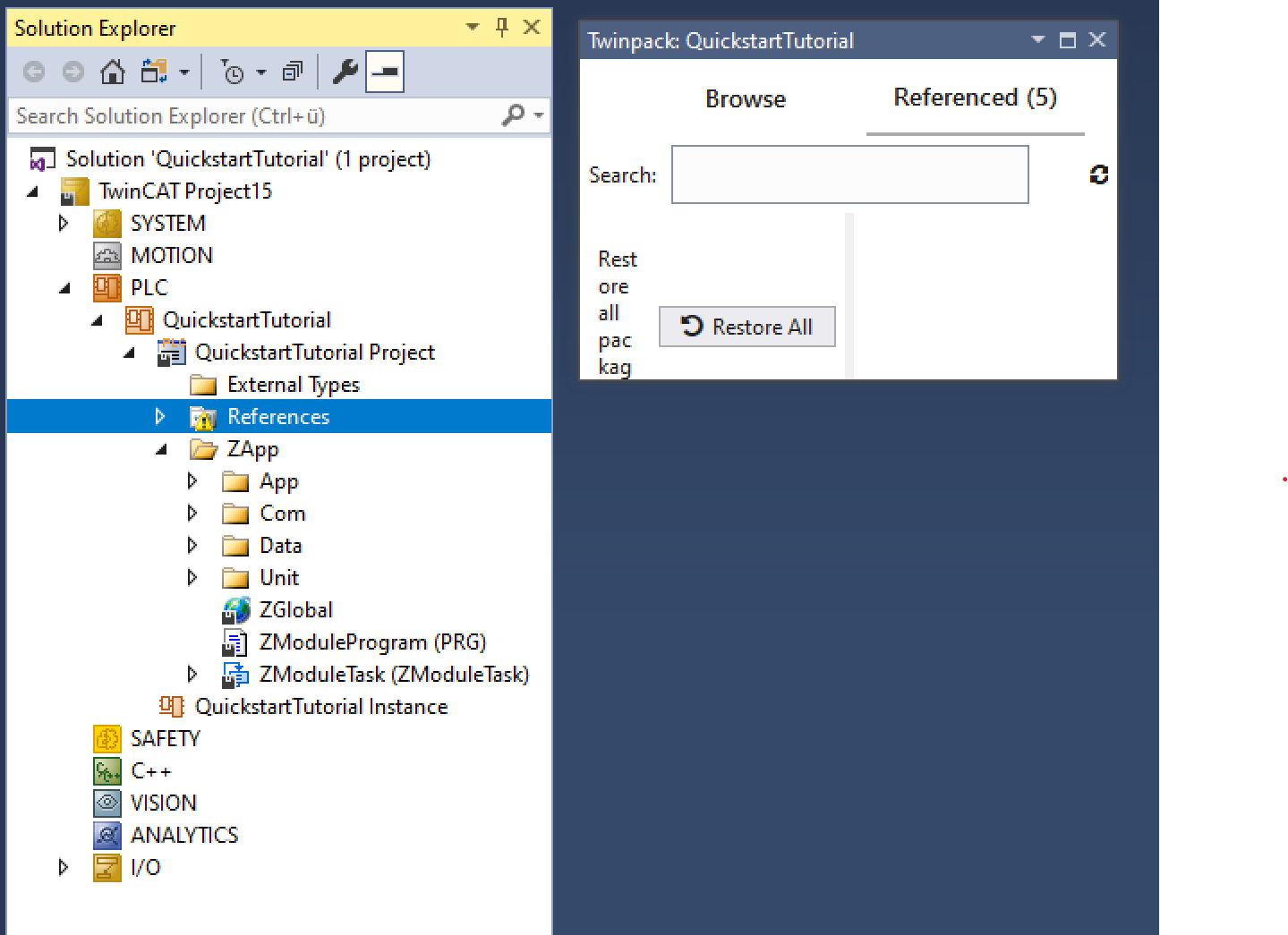
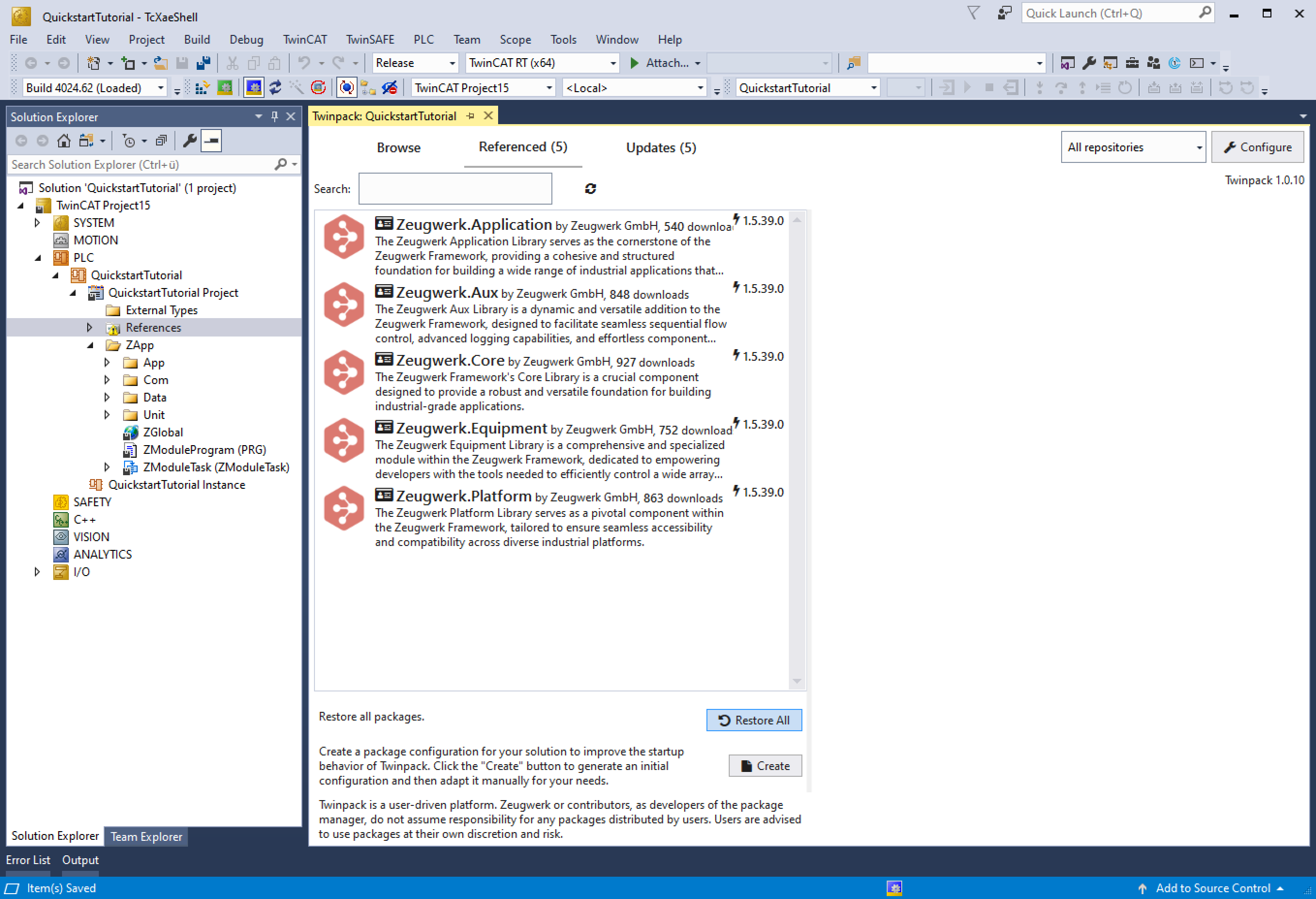
Referencesand openTwinpack Catalog - In Twinpack Catalog click on
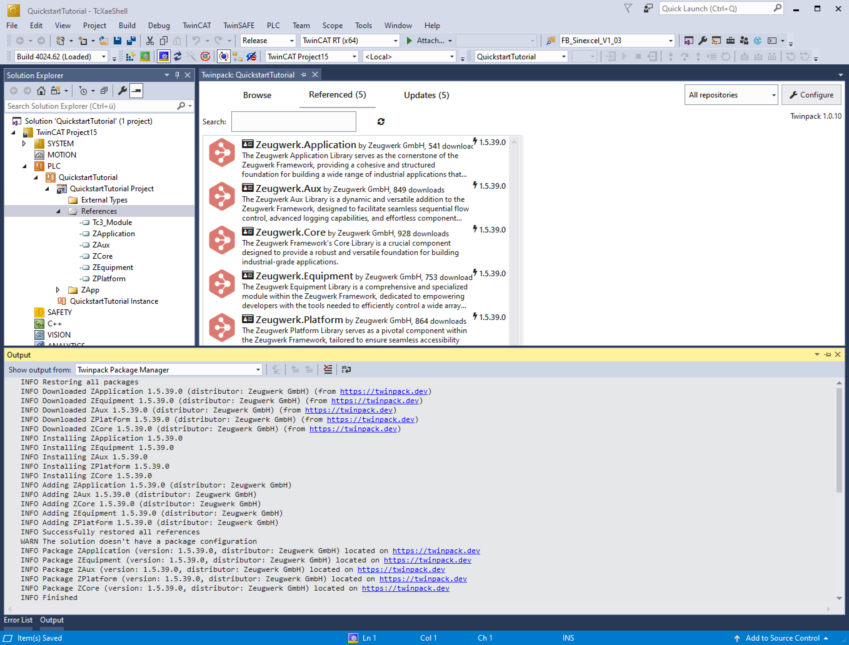
Referencedtab and at the very bottom of this window click onRestore All - Twinpack will now download all necessary libraries and install them automatically


Activate Zeugwerk Framework Trial License
Now as final step before we can activate our solution we need to check the Zeugwerk Framework license. For this
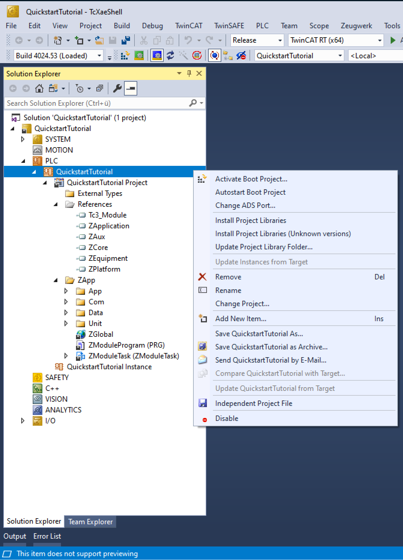
- Open
SYSTEMnode inSolution Explorerand openLicenseWindow - Open
Manage Licensestab and scroll to the very bottom - Activate
ZF1010 Zeugwerk Frameworklicense

Quickstart Tutorial
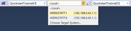
To activate the Quickstart Application, choose a TwinCAT Runtime of your choice (we often use Beckhoffs Usermode Runtime for internal/simulated tests) and click on Activate Configuration.
Now Switch to Run mode, Download the Application and click on Run. Now the application will boot up and is ready to use.
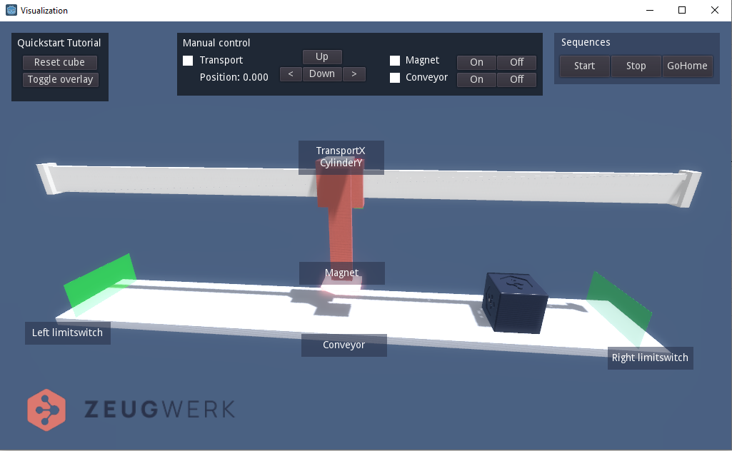
To make the tutorial fun to explore, we developed an interactive 3D visualization. You can start it by double-clicking on the Zeugwerk Quickstart Visualization icon on your desktop, or by navigating to the installation folder of the Development-Kit and starting Zeugwerk Quickstart Visualization from there. The tutorial doesn't require hardware of the utilized equipment. Instead, to make the tutorial more accessible, the framework together with a physics simulation in the visualization take care of simulating the hardware.
Exploring
The purpose of the machine, developed in the Quickstart Application, is to
- Move a cube from the left side to the right side by using a conveyor. The hardware that represents this conveyor is a digital output that is used to switch the conveyor on and off.
- Use an axis together with a vertical, pneumatic actuator and a magnet (again a digital output) to move the object from the right side to the left side. Two limit switches are used to detect the position of the actuator.
The (simulated) hardware that is utilized in the Tutorial are
| Name used in the PLC | Purpose | Equipment |
|---|---|---|
| TransportX | Axis | AxisPlcOpen |
| CylinderY | Pneumatic Actuator | ActuatorDigital |
| MagnetOn | Magnet | DigitalOutput |
| LimitSwitchLeft | Limit switch | DigitalInput |
| LimitSwitchRight | Limit switch | DigitalInput |
| ConveyorOn | Conveyor | DigitalOutput |
| CylinderYIsDown | Limit switch | DigitalInput |
| CylinderYIsUp | Limit switch | DigitalInput |
| CylinderYMoveDown | Limit switch | DigitalOutput |
| CylinderYMoveUp | Limit switch | DigitalOutput |
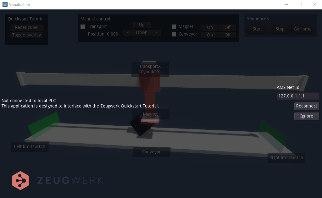
In the 3D-Visualization, you can use the buttons left and right to move axis Transport X. The actual position is displayed next to the Position label. In the PLC, this axis is controlled by a PLC open drive. If physical hardware was used, the internal implementation would utilize Beckhoff's NCMotion, in the simulation (aka digital twin) the drive is simulated by a software implementation. To give some visual feedback the simulated hardware is setup in a way to produce notable oscillations in the order of some microns, which is the reason why the axis is shaking a little bit if it is enabled.
The axis has a pneumatical cylinder (Cylinder Y) attached to it, which in turn can be moved vertically (Up and Down buttons). Two limit switches are used to detect the actual position of the actuator. On the lower end on this cylinder there is a magnet mounted which can be switched on and off (Magnet On and Off buttons) by an output of the PLC to attach the part and therefore be able to transport it. In the visualization in general the color red indicates that something is switched on and the digital IO, connected to it, has the state TRUE.
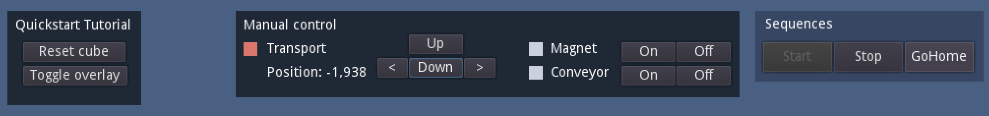


On the bottom of the machine there is a conveyor, which can be controlled by the On and Off buttons right beside the conveyor label.
On the left side of the conveyor there is a light barrier, which acts as a limit switch for the cube. If the light is red, the cube is intersecting the barrier and the state of the digital input is TRUE. If the light is green, the cube is not intersecting the barrier and the state of the digital input is FALSE.
The visualization is controlling the digital inputs of the PLC depending on the physical state.
LimitSwitchLeftandLimitSwitchRightare set by the visualization if the cube actually intersects the light barrier.CylinderYIsDownandCylinderYIsUpare set depending on the position of the piston.
Since the visualization is using a physics engine it might happen, that you come in a situation where the cube falls from the conveyor. In this case you can press Reset cube to make the cube magically reappear on the left side of the conveyor. In turn the limit switch LimitSwitchLeft should be enabled. Let us confirm this, by going back to your Twincat environment. Navigate to ZGlobal.Com.Unit.UselessBox.Publish.Equipment.LimitSwitchLeft. You now see three booleans, which have the following meaning
Simulatedis signaling if the input is simulated.Writeableindicates that this is a digital input (and not a digital output) and the state can be changed by an external application as the visualization.Enabledthis property represents the current state of the digital input, which should beTRUEif the cube intersects the light barrier.


Lets now start the conveyor by clicking the On button of the conveyor. The part should now move away from the light barrier and LimitSwitchLeft should signal go away (Enabled=FALSE). Stop the conveyor again by clicking its Off button. Resetting the cube with the Reset cube button will make the cube reappear on the left side and the signal is TRUE again.
Sequences
Every Unit that is instantiated in an application comes with a well-defined set of Standard States, which are linked to Sequences. The standard states, which are utilized by the framework are very similar to PackML. However the statemachine of the framework is much more flexible by allowing to use custom states and action. This is usually needed for processes outside of the main process of a given unit (adjustment, calibration, maintaince, ...).
Note that the current state of the QuickstartUnit is shown in the bottom-right corner of the visualization.
When starting the PLC the state of the QuickstartUnit is Init, which indicates that the Booting process of the machine was executed correctly.
Units now need to go through Homing state, only after successfully completing this state, units individually transition into Idle, which enables starting any other states of the unit.


Click the GoHome button in the the top-right corner to transition the machine into its Homing state, which will execute the Homing Sequence. Note that the visualization internally sets ZGlobal.Com.Unit.Quickstart.Publish.Request.GoHome=TRUE if this button is clicked. In homing, the following steps are taken through QuickstartSequenceGoHome.
- Switch off the magnet which eventually holds a cube
- Start the conveyor until a new cube stands at the very left of it and all other are falling over the edge on the right side
- Moves the vertical cylinder (CylinderY) up
- Positions the horizontal axis to 0.0mm with a speed of 10mm/s
In the second step the conveyor gets stopped and the sequence ends. If you take a closer look the axis Transport X you will notice that the horizontal axis is vibrating a little bit. This can also be observed by looking at the position. This is due to the noise simulation feature of the simulated axis that is used in the PLC. If the homing sequence has finished successfully, the state changes to Idle and the machine is ready for executing its Automatic sequence.
The latter sequence can be started by pressing the start button on the upper-right corner of the visualization. In this sequence the cube is transported to the right until the limit switch detects this part. After that the conveyor stops and Transport X moves to the right. Then, the Cylinder Y moves into its bottom position. The magnet switches on to "grab" the cube, the cylinder moves up and the axis transports the cube to the left side of the conveyor. The cylinder moves down, magnet off and cylinder up. Now the whole sequence starts from the beginning.
If you observe the state at the lower-right corner you see that the QuickstartUnit stays in its Automatic state, because it is coded in a way to loop endlessly.
Press the stop button or the halt button to eventually exit the automatic sequence (QuickstartSequenceAutomatic).
Haltswitches theHaltingflag in theautomatic sequenceso it can react to the request in a controlled way. It is implemented in a way to exit the automatic sequence after a full iteration of the sequence. The unit then ends up in theidle state. After halting the automatic sequence can be directly resumed.Stopgets out of theautomatic sequenceat the same PLC cycle as the button is pressed, then executed thestop sequenceand the unit eventually ends up in thestopped state. After stopping the machine it has to be homed in order to continue with the automatic sequence.
What's next
This initial tutorial showed you how to setup a application using the Quickstart Template to give you insights into how an application is usually structured when using the Zeugwerk Framework. Use our userguide to gain further inside into
- how a Units, Standard States and Custom States in the Zeugwerk-Framework context work
- how to develop applications from scratch with Zeugwerk Creator with the
Zeugwerk Applicationtemplate. - how to use unmanaged objects of the framework to integrate our well-tested classes into your existing PLC.
- how Zeugwerk Creator can be used to speed up your development cycle in general
- how Twinpack can be used to publish your very own libraries to public- or on-premises source-repositories
- and much, much more!